The installation works shall be performed by specialized crews licensed to perform installation works in accordance with a design approved following the established procedure, as well as taking into account the manufacturer’s recommendations.
Before installing:
- Check the date of manufacture. Boards from different batches may differ in tone.
- Make sure the boards are free from defects. If defects are found, please, contact Lato OJSC manager or their representative.
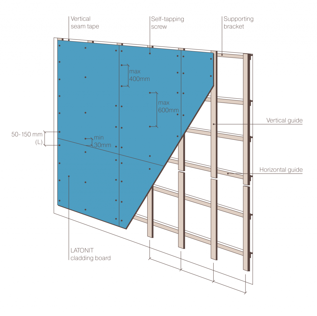
Suspended facade systems with an air clearance include a metal or wooden subassembly (framework), a heat insulation layer (if any), and a cladding board.
When installing a cladding screen, take into account thermal deformations of the subassembly, and thermal and moisture-induced deformations of the cladding. In this connection, EPDM tape must be used between the fiber cement board and the framework’s metal guides. The sealing tape is installed along the entire length of the vertical guide under the cladding board, ensures tight adherence of the cladding to the guide, reduces noise effect from cladding vibration, and also provides additional sealing to the system.
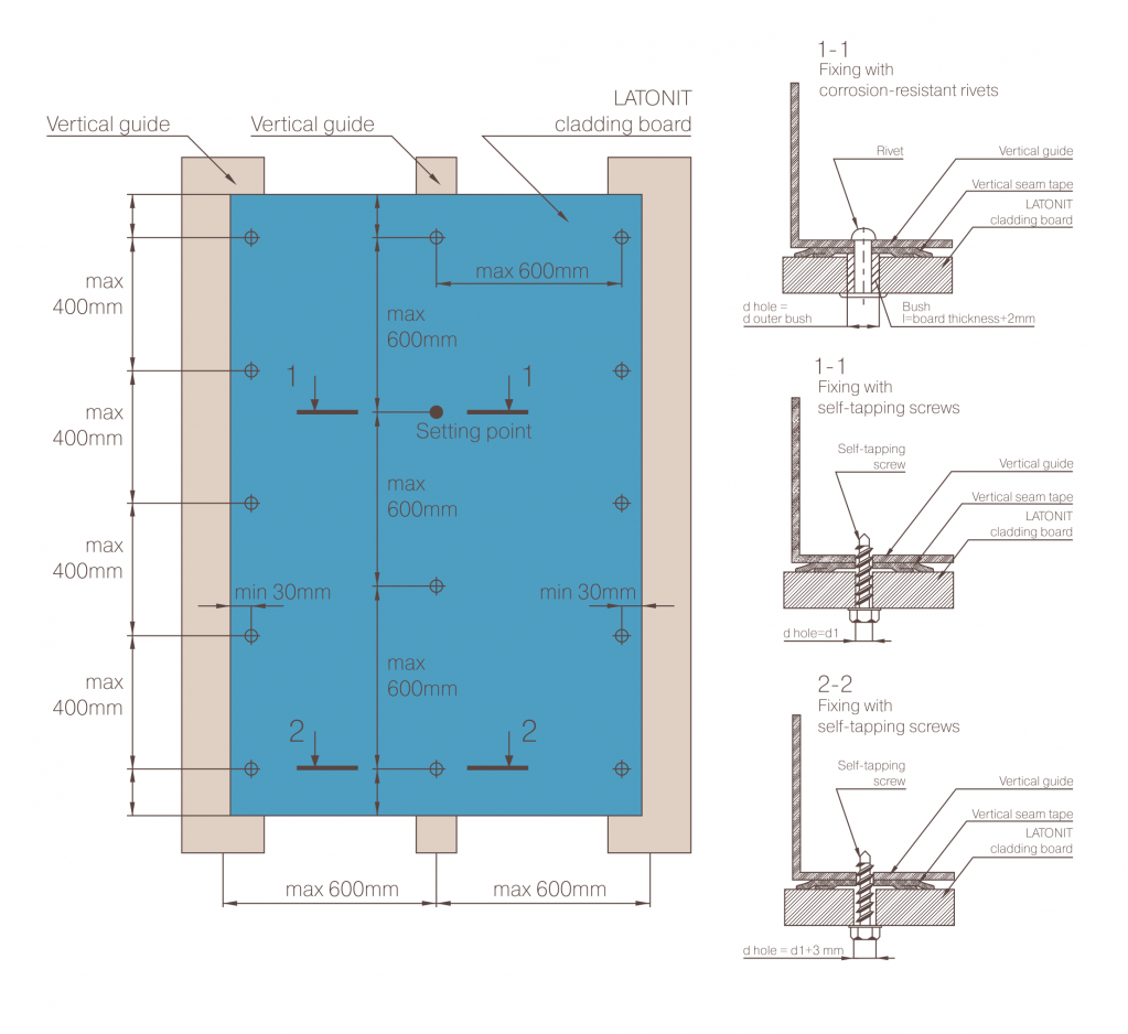
Cladding boards are installed using rivets or self-tapping screws from corrosion-resistant steel. When fixing a board, the distance between the self-tapping screws (rivets) and the board’s lower and upper edges shall be: for board length of up to 1 m - 50 mm, 1 m to 1,5 m - 100 mm, 1,5 m or longer - 150 mm. The distance between the self-tapping screws (rivets) to the board’s side edges shall be min 30 mm, the spacing between the self-tapping screws (rivets) along the board edge shall not exceed 400 mm; for board center fixing, spacing of max 600 mm is allowed.
To preclude possible board failures, rivets must be placed in the holes in the board fixing points in combination with a bush that prevents pressing the board being installed against the guide. The length of the bush used shall correspond to the cladding board thickness +2 mm. When fixing boards on a façade with self-tapping screws, overtightening is not allowed in order to preclude mechanical damage resulting from thermal and moisture-induced deformations arising during façade operation under natural conditions. The process gap between the board sides is 6 to 10 mm.
Installation diagram. Vertical arrangement of boards

| Board lenght | Distance from the board's lower and upper edges (L) | Distance to the screws from the board's left and right edges |
| ≤1000 mm | 50 mm | min 30 mm |
| 1000 – 1500 mm | 100 mm | |
| ≥1500 mm | 150 mm |
Cladding board fixing diagram. Vertical arrangement

| Board lenght | Distance from the board's lower and upper edges (L) | Note |
| ≤1000 mm | 50 mm | The distance from the axis of a self-tapping screw (rivet) to the guide edges shall be at least 2d, where d is the diameter of the self-tapping screw (rivet) |
| 1000 – 1500 mm | 100 mm | |
| ≥1500 mm | 150 mm |


